There’s a multitude of guitar FX pedals out there, but many of them are quite expensive. For those with some technical skill and a soldering iron, there’s an alternative: building your own pedals from a kit. A large selection of kits is sold by Musikding, and I recently ordered the Katana (Keeley Katana-style boost) and Plexi (Wampler Plexi Drive-style overdrive) from them. Here are a couple of pictures of the Katana build process. The total time required was about 2 hours.
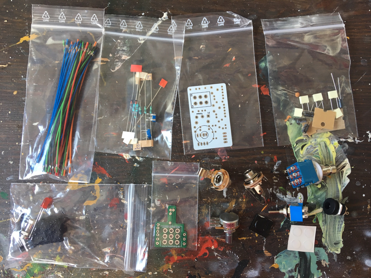
The contents of the kit. The wires are already stripped, and the resistors are labelled.
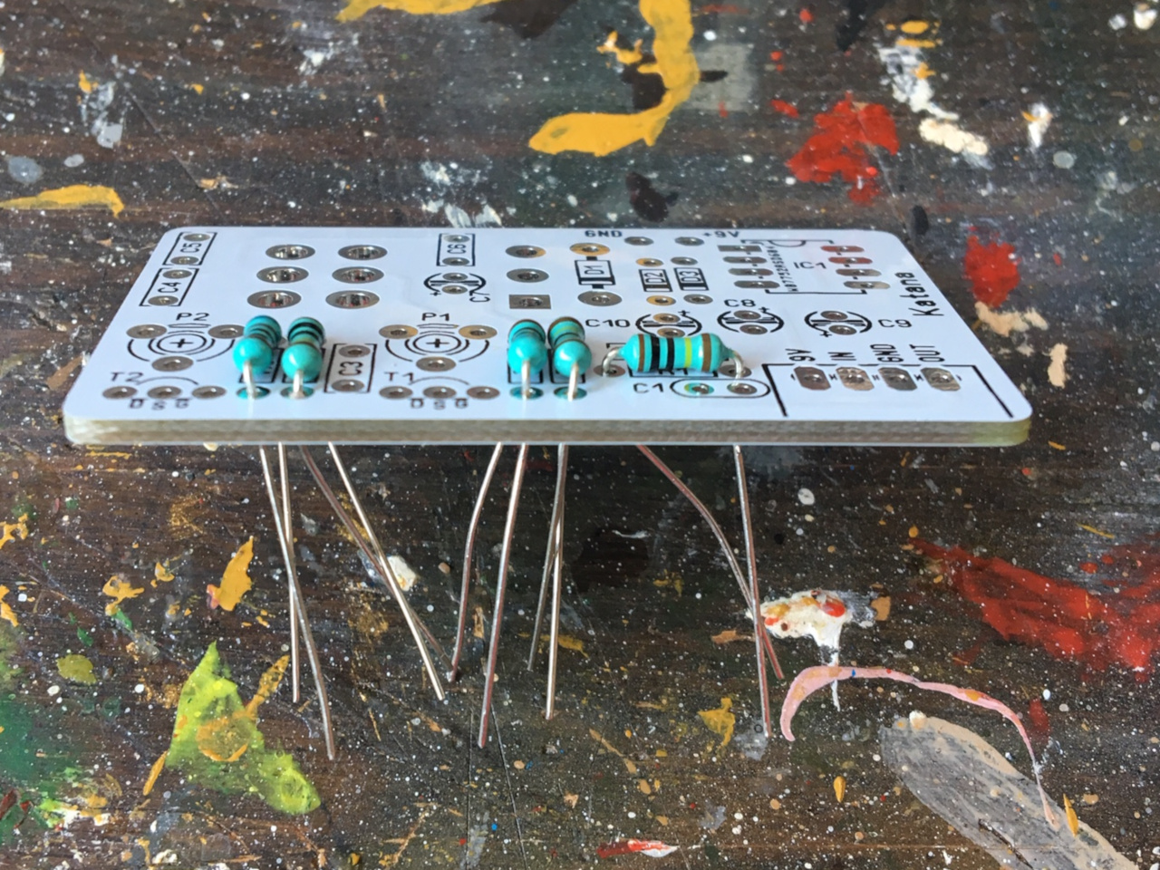
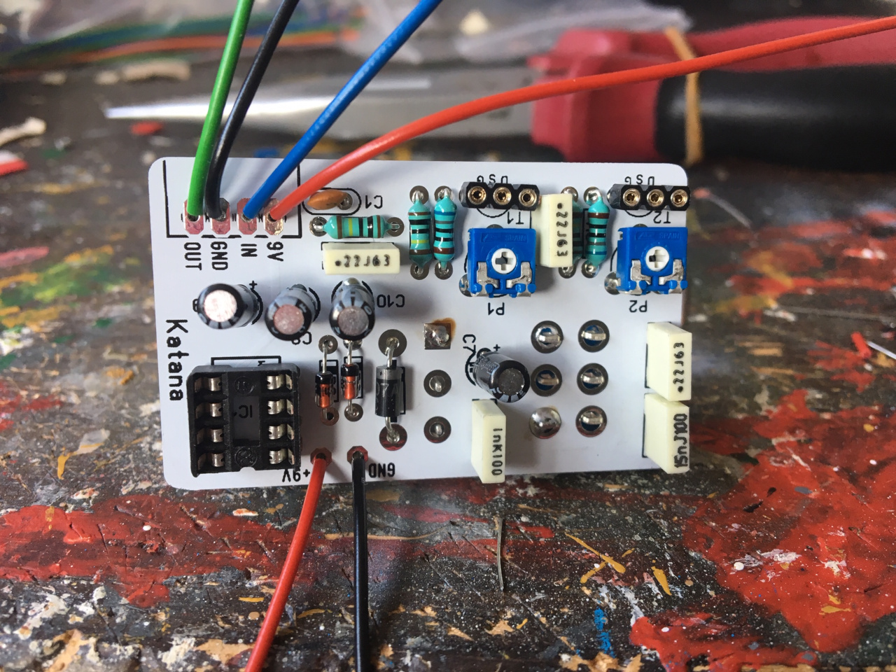
The components should be soldered onto the PCB in order of height, so resistors and diodes go in first.
Other low components are the transistor and IC sockets and the trim pots for the FET transistors.
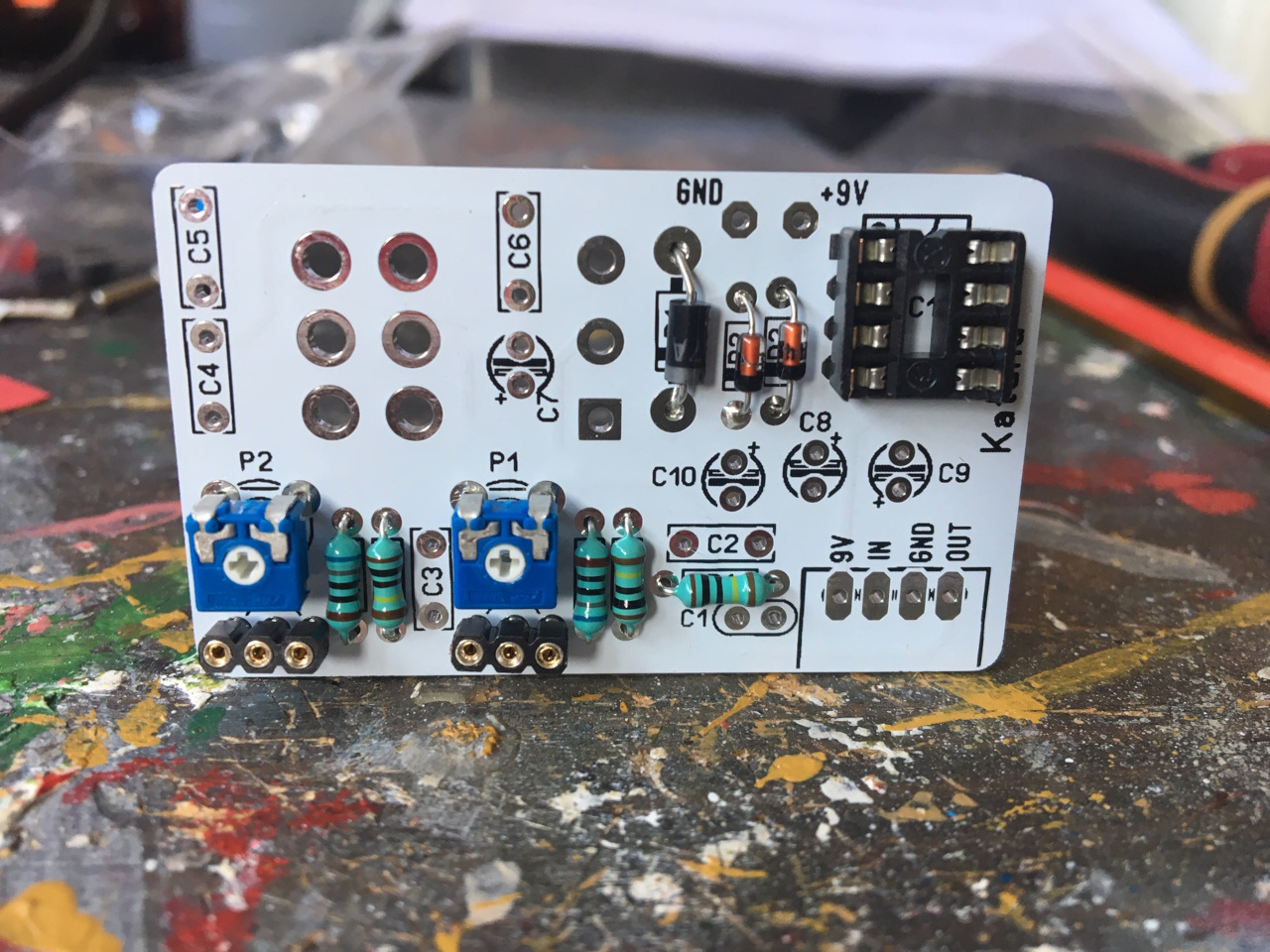
The PCB is completed. Capacitors and wires have been added, as well as the potmeter and switch (on the other side). Only one contact on these has been soldered in at this point, as this allows for some adjustment after the PCB has been mounted to the case.
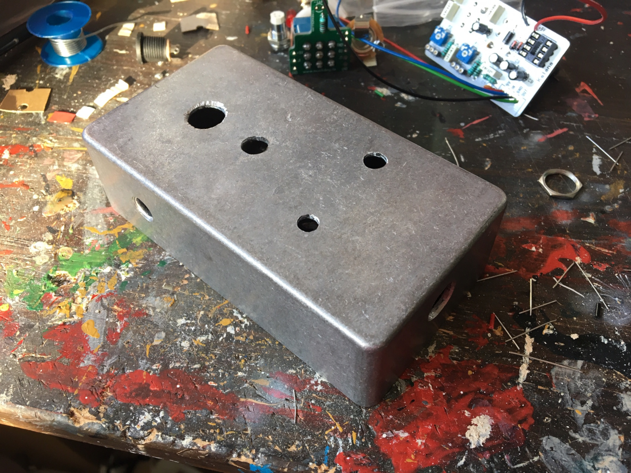
The next step is drilling the case. You can buy pre-drilled cases from Musikding, but if you plan on building multiple pedals or want to use different colored cases, I recommend drilling yourself. You need a couple of different drill sizes, and a drill press is recommended, although I did the drilling with a hand-held drill. Use a center punch to guide the drill, and measure everything twice to make sure the holes are the correct diameter and in the right place. I made the mistake of drilling the footswitch hole too close to the input/output jack holes, and had to drill a second hole (not shown yet).
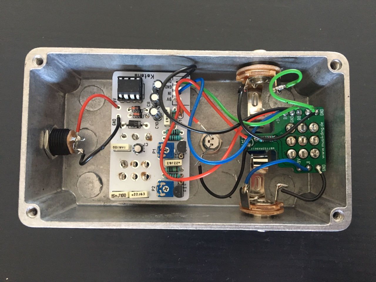
Assembly and wiring completed. I don’t use batteries, so I didn’t add the battery clip. I also didn’t trim the wires from the main to the footswitch PCB, doing so would make everything look a bit neater. This picture was taken after the first test, with op-amp and transistors already added. The drain voltage of the transistors needs to be set. This is done by measuring voltage between the drain (D) leg of the transistor and a ground point, e.g. on the footswitch PCB. For this kit, the recommendation is to set it close to 9V. You can also see that I needed to add wires from the footswitch PCB to the LED, as I had to relocate the footswitch after the LED hole had been drilled.
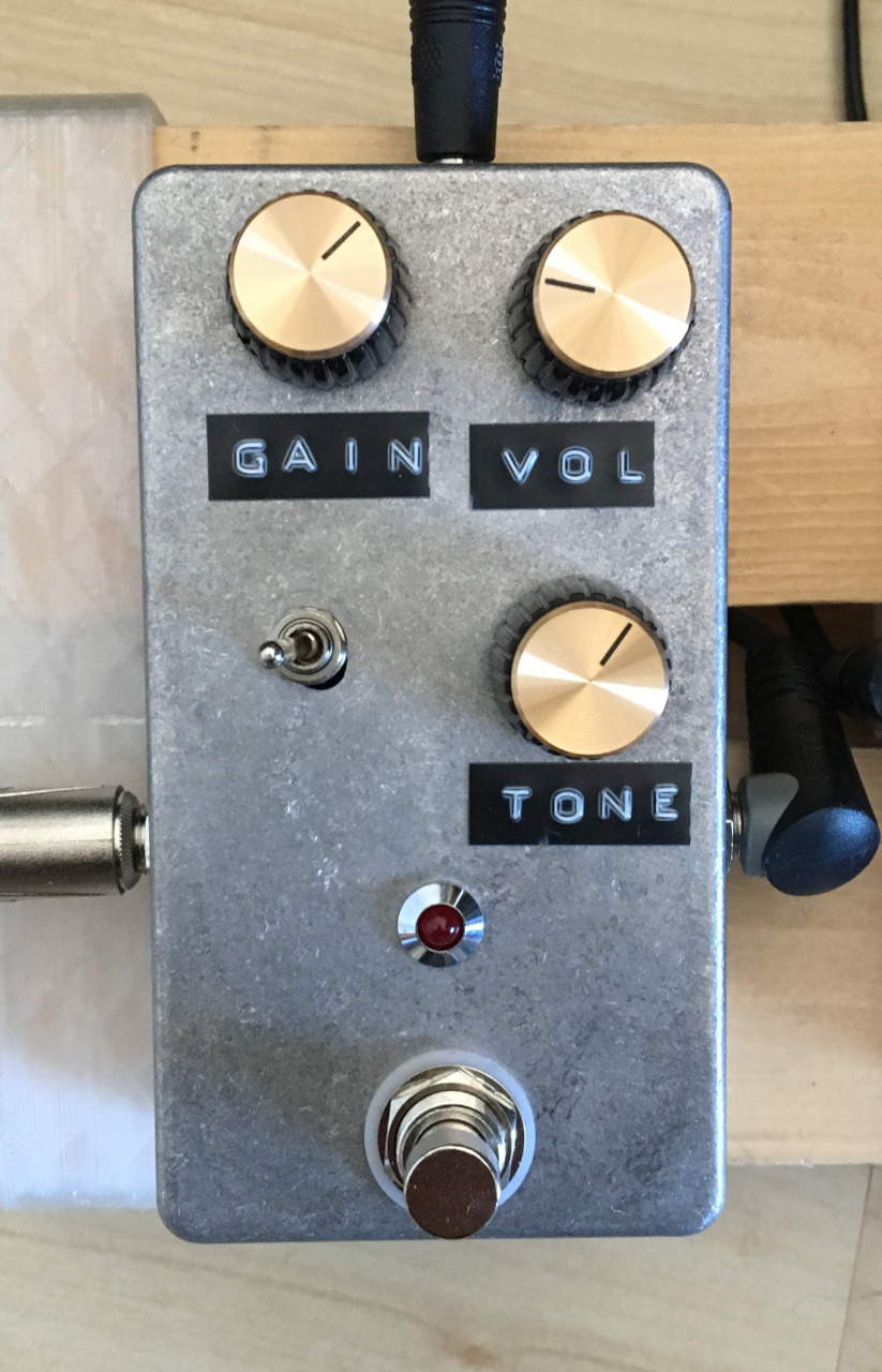
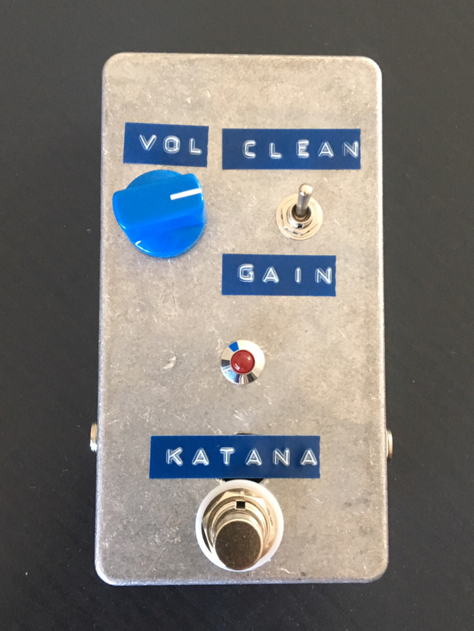
The completed pedal. Musikding sells a large variety of knobs. I used a simple embossing label maker for the labels (one of them crudely covering up the extra hole), but you could use printable decal transfer sheets if you want a more professional look.
The other pedal that I built is a copy of the Wampler Plexi Drive. This one also went together pretty quickly. I once again goofed up while drilling, hence the knobs aren’t aligned nicely.